
Enabling Antibody-drug conjugate manufacturing using single-use systems in downstream – Extractables study demonstrates a good fit
Antibody drug conjugates offer tremendous therapeutic potential and the market for ADCs is expected to expand rapidly. However, antibody-drug conjugate manufacturing presents both technological and logistical challenges.
Antibody drug conjugates are composed of three parts: an antibody specific for the tumor associated antigen, which has restricted expression on normal cells, a cytotoxic agent designed to kill target cells when internalized and released and, a chemical linker to attach the cytotoxic agent to the antibody. New linker systems are designed to be stable in circulation and release the cytotoxic agent after being internalized by the targeted cells. Because the cytotoxic agent is delivered in such small quantity, it must be powerful enough to kill the tumor cells. Therefore, the potency of these cytotoxic agents is 100-1000 fold more potent than cytotoxic agents delivered as free drugs.
One challenge in manufacturing is caused by the very factor that makes them a successful therapeutic, the cytotoxins. When manufacturing ADCs, potential operator exposure to the cytotoxins is a concern. Another issue is management of the toxic wastewater generated by cleaning procedures.
The high potency of ADCs also means that not a great deal of material must be generated, therefore manufacturing must accommodate small batch sizes and most often a multi-product facility. This also means ensuring quick changeover time without increasing risk of contamination between product batches.
Interestingly, single-use systems could address several of these issues and offer manufacturing advantages with ADC production. For example, single-use would reduce potential operator exposure to toxins and would lower the risk of cross-product contamination. Small batch sizes are also a good fit for single-use technologies as they are more cost-effective at this scale and facilitate multi-product facilities by permitting reduced changeover time with minimal contamination risk.
However, despite all the potential advantages, there is concern about the organic solvents used in ADC manufacturing and the possibility that these harsh chemicals could cause the release of leachables into the product.
I am pleased to share the following guest blog that looks at the issue of leachables in two downstream single-use products. The blog describes studies performed on disposable chromatography column housings and disposable flow paths by GE Healthcare. The extractables studies were performed with two solvents commonly used in the ADC cytotoxin conjugation step, DMA and DMSO. The studies were designed to ensure that conditions were exaggerated compared to existing ADC manufacturing processes. Extractable organic compounds and trace elements from the single‑use components were identified and semi‑quantitated with a complementary set of analytical techniques. The low levels of extractables found in this study support the use of single-use technologies in ADC processes.
Extractables studies for single‑use systems used in antibody‑drug conjugate manufacturing
Introduction
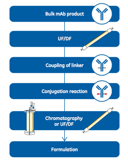
Antibody-drug conjugates (ADC) are biotherapeutic molecules consisting of a cytotoxin coupled to a monoclonal antibody (mAb) by a linker. The target specificity of the mAb enables delivery of the toxic drug to the cancer cells while minimizing collateral damage to healthy cells. mAbs used in ADC production are typically manufactured according to traditional processes, including purification via protein A-platform processes (1, 2). Before coupling the linker, the mAb needs to be transferred to a suitable solution. This solvent exchange is normally performed by an ultrafiltration/diafiltration (UF/DF) operation. After the linker coupling reaction, the next step is the conjugation reaction, which couples the cytotoxic drug. Figure 1 provides an example workflow for manufacturing an ADC from a bulk mAb product. Conjugation reactions are typically performed in a solvent containing either N,N-dimethylacetamide (DMA) or dimethyl sulfoxide (DMSO) (3). Single-use systems are well suited to ADC manufacturing for several reasons. Importantly, SU systems minimize operator exposure to toxins while also protecting the product from
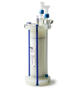
the operator and environment. The high potency of ADCs means that relatively small amounts of products need to be produced per batch. The small batch sizes are well suited for incorporation of single-use technology, which provides a cost- efficient solution for multi-product manufacturing. In addition to the lower upfront capital cost compared with reusable systems, single-use technology is quicker to start using because it is supplied ready to use. Cleaning and cleaning validation between manufacturing campaigns is unnecessary, and the potential for carryover of cytotoxin from one batch to another is minimized. Because cleaning is not performed, single-use technology minimizes the volume of contaminated waste that must be handled and disposed of. In order to support the adoption of single-use technology in ADC production, relevant extractables information is needed. Therefore, extractables studies were performed on two GE single-use products for chromatographic purification – the ReadyToProcess column and the disposable flow path, ÄKTA ready Flow Kit (Fig 2).

Materials and methods
The goal of the extraction studies was to characterize extractables profiles with equipment and conditions relevant to current ADC manufacturing processes. To that end, the studies were designed and performed with advice from customers who use disposables in their ADC processes.
Extractables study design
The extractables studies were designed with consideration for test conditions representing a worst-case scenario and for appropriate analytical techniques (3). Solvent concentrations used in typical cytotoxin conjugation reactions were exaggerated, as were surface area-to-volume ratios, temperatures, and contact times for chromatography following the conjugation step (Table 1). The experiment was set up to ensure complete contact with all wetted parts. Control samples of DMSO and DMA solution that had been stored at the same conditions but not in contact with the test article were included as blank references. The extractions and preparation of control samples were performed at Toxikon Europe NV.
| Standard Process | Study Design | |
|---|---|---|
| Solvent concentration (DMSO or DMA) in conjugation reaction (%) | 10-15 | 15 |
| Temperature for chromatography (°C) | 20-25 | 30 |
| Contact time for chromatography (h) | 6-8 | 24 |
| Surface area-to-volume ratio for chromatography | Flow velocity at running conditions will yield large volume | The smallest column size (1 L) was used to obtain the highest possible area-to-volume ratio. All inlets and outlets of a smallest size flow kit were extracted to obtain the highest possible area-to-volume ratio |
Process set-up – column housings
The test articles were two 1 L ReadyToProcess column housings (Fig 3). Because of the wide variety of resins that could be used,
this study was limited to the column hardware. The smallest size ReadyToProcess column was selected to ensure the highest possible surface area-to-volume ratio, representing a worst case. The wetted materials of construction are listed in Table 2. Tubing was connected to the inlet of each column. The other end of each piece of tubing was placed into a volumetric cylinder containing 1 L of either 15% DMA or 15% DMSO. The extraction solutions were pumped into the columns (test articles) using a peristaltic pump. After filling, the tubing was removed, and the inlet and outlet tubes of the columns were clamped. The filled columns were placed upright on an orbital shaker (19 mm orbit diameter) and incubated at 100 rpm for 24 h at 30°C. After incubation, the clamps from the inlet and outlet tubes were removed. The extracts were transferred to separate bottles by applying nitrogen pressure. The control samples were prepared by pumping 1 L of each solution through two pieces of tubing from a volumetric cylinder into a glass bottle, using a peristaltic pump. The bottles were placed on an orbital shaker alongside the filled columns and agitated at 100 rpm for 24 h at 30°C. After incubation, extraction solutions from the test articles and control samples were collected for analysis, divided into separate containers for the different analytical techniques, and stored at 5°C.
Process set-up – disposable flow paths
| Materials | Sources |
|---|---|
| Polypropylene (PP) | Tube, lids, TC outlet, TC and hose connections, nets, net rings, support nets, hose |
| Polyetheretherketone (PEEK) | Plug, net holder, nozzle tube |
| Polyolefin (POE) | Hose |
| Ethylenepropylenediene monomer (EPDM) | TC gasket |
| Fluorocarbon rubber (FPM/PKM) | O-rings |

The test articles were two ÄKTA ready Low Flow Kits. The smallest size flow kit was selected to ensure the highest possible surface area-to-volume ratio, representing a worst case. The wetted materials of construction are listed in Table 3. The open ends of the tubings of a Low Flow Kit (Fig 4) were connected to each other using EPDM gaskets and TC 25 clamps. The pump tubing of each flow kit was connected to a peristaltic pump, and the pump was used to fill the flow kit with 700 mL of either 15% DMA or 15% DMSO. During filling, the air trap of the flow kit was mounted at the highest position in order to let the air escape from the flow kit and to make sure that all surfaces were wetted with extraction solvent . Subsequently, the solution was circulated through the flow kit for 24 h at 30°C in an incubator (Fig 4). Control samples were prepared by filling a glass bottle with 500 mL of either extraction solution and placing in the incubator at 30°C for 24 h. After incubation, extraction solutions from the test articles and control samples were collected for analysis, divided, and stored in the same manner as the solutions from the column housing study.
| Materials | Sources |
|---|---|
| Polypropylene (PP) | Connections, housings, and other parts |
| Polyetheretherketone (PEEK) | Plug, T- and Y-connections |
| Ethylenepropylenediene monomer (EPDM) | TC gasket, pressure membranes, O-rings |
| Polyamide (PA) | Housing airtrap |
| Thermoplastic elastomer (TPE) | UV cell, double mould |
| Polymethylpentene (PMP) | Flowmeter parts |
| Silicone (Si) | Hose |
| Titanium (Ti) | Cond cell ring |
| Polytetrafluoroethylene/ silicone (PTFE/Si) | Pump hose |
Analytical methods
Two classes of extractable compounds were analyzed – organic compounds and a spectrum of elements. Organic compounds were identified and semi-quantitative results obtained with liquid chromatography-mass spectrometry (LC-MS) and gas chromatography-mass spectrometry (GC-MS) methods. Screening methods for volatile, semi-volatile, and nonvolatile compounds (VOC, SVOC, NVOC) are listed in Table 4. Analyses of organic compounds were performed by Toxikon Europe NV in Leuven, Belgium. Elemental analysis was performed by ALS Scandinavia AB in Luleå, Sweden by inductively coupled plasma/sector field mass spectrometry (ICP-SFMS). An overview of the test methods is provided in Table 4.
| Analysis* | Target compounds | Typical compounds that could be detected if present | Explanation |
|---|---|---|---|
| * MS = mass spectrometry; GC = gas chromatography; HS = headspace; APCI = atmospheric pressure chemical ionization; ICP-SFMS = inductively coupled plasma/sector field mass spectrometry; UPLC = ultra performance liquid chromatography | |||
| HS-GC-MS | Volatile organic compounds (VOC) | Residual monomers and solvents, small polymer degradation products | Combination of headspace (HS) sampling and GC-MS analysis allows identification of a volatile compound |
| GC-MS | Semi-volatile organic compounds (SVOC) | Process lubricants, plasticizers, antioxidants, polymer degradation products, high boiling solvents | For detection of organic compounds that are not sufficiently volatile for detection using HS-GC-MS but are volatile enough for GC-MS detection |
| LC-MS APCI, pos and neg mode | Nonvolatile organic compounds (NVOC) | Anti-oxidants, fillers, plasticizers, polymerization or hydrogenation catalysts, polymer additives, and nonvolatile degradation products of those compounds | A rapid and sensitive UPLC method in combination with high resolution accurate mass (HRAM) mass spectrometry. APCI mode chosen as most appropriate, because most extractables from a polymer are relatively small molecules with medium to low polarity |
| ICP-SFMS | Elements | Metals in fillers, pigments, catalyst residues | Method allows determination of multiple elements by scanning for them simultaneously |
Results and discussion
ReadyToProcess column housings
No organic extractable compounds were found above reporting limit with HS-GC-MS or GC-MS in the extraction samples with 15% DMA or 15% DMSO. The results with LC-MS showed one organic compound that was present in both 15% DMA and 15% DMSO. The extractable compound was assigned a Confirmed identity level as an Identified compound related to a curing agent used with elastomeric material. The concentration was estimated below 200 μg/L (ppb) in both extraction solvents (i.e., less than 200 μg/ReadyToProcess column). Analysis with ICP-SFMS showed low levels of a few extractable elements. The most abundant were calcium (< 100 μg/L) and magnesium (< 25 μg/L), followed by zinc (< 10 μg/L) and barium (< 2 μg/L). The extractable elements were found at a similar level in both 15% DMA and 15% DMSO.
ÄKTA ready Low Flow Kit
The results showed five organic extractable compounds above reporting limit with HS-GC-MS, GC-MS, and LC-MS. Two of the compounds were found in 15% DMA, and three compounds were found in 15% DMSO. All five extractable compounds were assigned a Confirmed identity level as Identified compounds related to polyamide and silicone materials and one solvent . The highest abundant extractable compound was present at a concentration below 600 μg/L (i.e., 410 μg/Low Flow Kit , because the extraction volume was 700 mL). Analysis with ICP-SFMS showed that the most abundant extractable element was silicon, which was present below 9 mg/L (ppm). Additionally, calcium, barium, zinc, and copper were found at lower levels. The extractable elements were found at a similar level in both 15% DMA and 15% DMSO.
Assessment of results
A general toxicity and safety evaluation of extractable compounds as a worst case was carried out . It can only be general, because the specific details regarding the route of administration, dosage level, or toxicity of the proposed drug compounds will differ between different ADC’s. Toxicological information and a derived Risk Index (RI) for five out of the six identified extractable compounds were listed in a reference containing compiled safety impact information (4). In that reference, risk indices were obtained by subjecting toxicological safety data such as NOELs (no observed effect levels), NOAELs (no observed adverse effect levels), lowest published toxic dose, and others to a systematic evaluation process using appropriate uncertainty factors. A risk index value represents a daily intake value for life- long intravenous administration. An additional RI value was derived for the sixth identified extractable compound from a reported NOAEL value and appropriate uncertainty factors.
Assumptions for the assessment were:
- A chromatography system for this assessment is comprised of the column housing and the flow kit . All extractables from the chromatography system end up as impurity in the ADC product
- Load of ADC on the chromatography column is 5 g/L, considered a low load, representing a worst case.
- Dosage to a patient is 12 mg/day, considered a high dose, representing a worst case
The numbers used in calculations for the assessment are shown in Table 5.
| Extractable compound | Highest result on extractables (μg/system) | Column volume (L) | Load (g/L) | Mass of ADC (g) | Daily dosage ADC (mg/d) | Effective dosage extractables (μg/d) | RI exposure limit (μg/d) |
|---|---|---|---|---|---|---|---|
| Related to polyamide² | 410 | 1 | 5 | 5 | 12 | 0.984 | 21,000 |
| Related to curing agent¹ | 190 | 1 | 5 | 5 | 12 | 0.456 | 560 |
| Related to silicone² | 150 | 1 | 5 | 5 | 12 | 0.360 | 1,750 |
| Solvent² | 25 | 1 | 5 | 5 | 12 | 0.060 | 50,000 |
| Related to silicone² | 8.4 | 1 | 5 | 5 | 12 | 0.020 | 700 |
| Related to silicone² | 7 | 1 | 5 | 5 | 12 | 0.017 | 11,200 |
Assessment of the results according to the listed assumptions shows that the potential exposure to extractables is well below the risk index for each extractable compound. Therefore, extractables from ReadyToProcess column housing and ÄKTA ready Flow Kit should pose no safety concern for use in ADC manufacturing within the conditions of this study.
Conclusions
The low levels of extractables found in this study demonstrate chemical compatibility of ReadyToProcess columns and ÄKTA ready Flow Kits with two organic solvents typically employed in ADC manufacturing processes, DMSO and DMA. Detailed results of these studies are added to the validation guides for these two single-use components to supplement existing data generated with aqueous solvents and ethanol. Along with other single-use components and systems, ReadyToProcess columns and ÄKTA ready Flow Kits offer a solution to some of the main challenges in ADC manufacturing. Single-use technology provides a closed system to protect both operator and product and reduces the risk of cross-contamination between batches. Components are supplied ready to use without cleaning, and cleaning between batches is unnecessary, saving time, handling, and water. In addition, single-use systems offer lower upfront capital expenditures, greater flexibility, and a smaller footprint compared with traditional technologies.